Fletcher: How to refer to CeTZ anchors inside nodes?

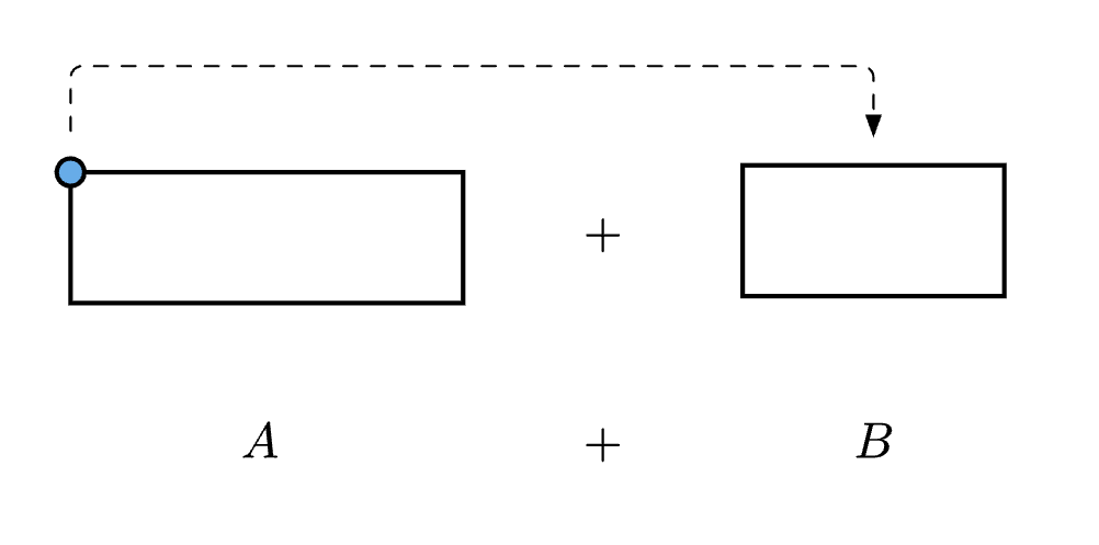
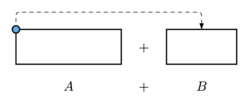
I use Fletcher with CeTZ given the convenience of aligning nodes in a diagram, however, I cannot find a “nice” way to access anchor points of CeTZ content within a diagram. In the example below I intend to draw an edge from node <n_1> to the second rectangle, specifically from its north-west anchor point.
The closest I can get is by manually using the shift option for the edge at one end, of course, this is not robust if the size of the rectangles change.

#import "@preview/fletcher:0.5.8": diagram, node, edge
#import "@preview/cetz:0.4.0" as cetz: draw

#let lighten_col = 40%
#figure()[
  #diagram(
    spacing: 14pt,
    node((0,0), 
      name: <n_1>,
      cetz.canvas({
        import draw: *
        rect((0,0), (3,1), name: "rect")
        circle(("rect.north-west"), radius: 3pt, fill: blue.lighten(40%));
      })
    ),
    node((1,0),$+$),
                                    // Shift option here:
    edge(<n_1>, "u,r,r,d", "--|>", shift:(-41pt, 0pt)),
    node((2,0), 
      cetz.canvas({
        import draw: *
        rect((0,0), (2,1))
      }),
    ),
    // Some other nodes...
    node((0,1),$A$),
    node((1,1),$+$),
    node((2,1),$B$),
  )
]

For clarity it would be great if I could use something like edge(<n_1.north-west>, ... for the edge drawing.

1 Like

It looks like the poly steps "u,r,r,d" are just wrong as soon as you use the node anchor <n_1.north-west> instead of just the name <n_1> of the node? Is this intended or a bug, @Jollywatt?

You can get around this limitation by only using node anchors and coordinates relative to the node anchors to specify the poly path. This is somewhat verbose, but it does not require any manual adjustment. It also requires the node-inset to be zero, otherwise the north-west anchor will start too far on the left of the node.

The circle you are attaching to the rectangle in node <n_1> causes the entire node to have a larger bounding box (than expected). This will affect the node anchors (you can nicely see this with debug: true). I therefore removed the circle from the CeTZ canvas and created an additional node at the position <n_1.north-west>.

Here is the code (with a few things just commented out)
#import "@preview/fletcher:0.5.8": diagram, node, edge
#import "@preview/cetz:0.4.0" as cetz: draw

#let lighten_col = 40%
#figure()[
  #diagram(
    // debug: true,
    spacing: 14pt,
    node-inset: 0pt,
    node((0,0),
      name: <n_1>,
      shape: rect,
      cetz.canvas({
        import draw: *
        rect((0,0), (3,1), name: "rect")
        // circle(("rect.north-west"), radius: 3pt, fill: blue.lighten(40%));
      })
    ),
    node(<n_1.north-west>, circle(fill: blue.lighten(40%), stroke: black, radius: 3pt)),
    node((1,0),$+$),
    
    edge(
      <n_1.north-west>,
      (rel: (0, -1), to: <n_1.north-west>),
      (rel: (0, -1), to: <n_2.north>),
      <n_2.north>,
      "--|>"
    ),
    // edge(
    //   <n_1>,
    //   "u,r,r,d",
    //   "--|>",
    // ),
    
    node((2,0), 
      name: <n_2>,
      cetz.canvas({
        import draw: *
        rect((0,0), (2,1))
      }),
    ),
    
    // Some other nodes...
    node((0,1),$A$),
    node((1,1),$+$),
    node((2,1),$B$),
  )
]
1 Like