I currently have the following diagram
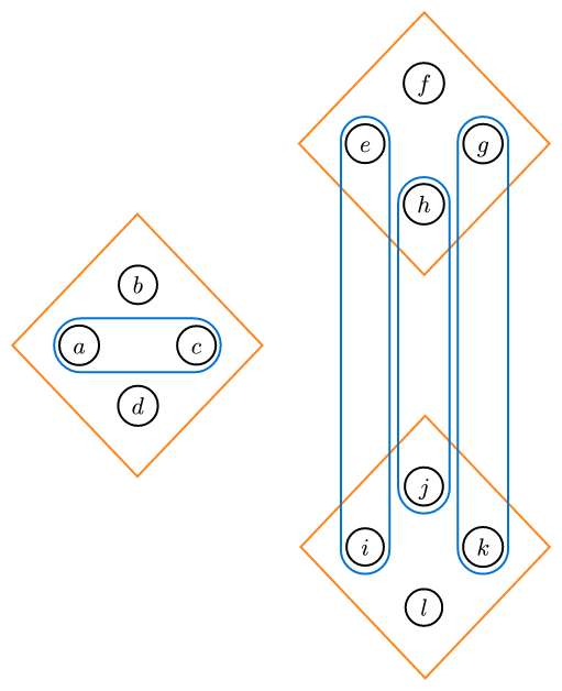
from the code:
#set page(
  width: auto,
  height: auto,
  margin: 2mm,
)

#import "@preview/fletcher:0.5.8" as fletcher: diagram, node, edge, cetz
#import fletcher.shapes: circle, pill, diamond

#diagram(
  debug: 0,
  node-shape: circle,
  node-inset: 1.5mm,
  node-outset: 0mm,
  node-fill: none,
  axes: (ltr, btt),
  let diam-radius = 0.6,
  let v2-pos = (3, 2),
  let v3-pos = (3, -2),
  node((-diam-radius, 0), $a$, stroke: black, name: <a>),
  node((diam-radius, 0), $c$, stroke: black, name: <c>),
  node((0, diam-radius), $b$, stroke: black, name: <b>),
  node((0, -diam-radius), $d$, stroke: black, name: <d>),
  //
  node((v2-pos.at(0) - diam-radius, v2-pos.at(1)), $e$, stroke: black, name: <e>),
  node((v2-pos.at(0) + diam-radius, v2-pos.at(1)), $g$, stroke: black, name: <g>),
  node((v2-pos.at(0), v2-pos.at(1) + diam-radius), $f$, stroke: black, name: <f>),
  node((v2-pos.at(0), v2-pos.at(1) - diam-radius), $h$, stroke: black, name: <h>),
  //
  node((v3-pos.at(0) - diam-radius, v3-pos.at(1)), $i$, stroke: black, name: <i>),
  node((v3-pos.at(0) + diam-radius, v3-pos.at(1)), $k$, stroke: black, name: <k>),
  node((v3-pos.at(0), v3-pos.at(1) + diam-radius), $j$, stroke: black, name: <j>),
  node((v3-pos.at(0), v3-pos.at(1) - diam-radius), $l$, stroke: black, name: <l>),
  // 4-element sets partition
  node([], enclose: (<a>, <b>, <c>, <d>), stroke: orange, shape: diamond),
  node([], enclose: (<e>, <f>, <g>, <h>), stroke: orange, shape: diamond),
  node([], enclose: (<i>, <j>, <k>, <l>), stroke: orange, shape: diamond),
  // Easy 2-element sets
  node([], enclose: (<a>, <c>), stroke: blue, shape: pill),
  node([], enclose: (<h>, <j>), stroke: blue, shape: pill),
  node([], enclose: (<e>, <i>), stroke: blue, shape: pill),
  node([], enclose: (<g>, <k>), stroke: blue, shape: pill),
  // 2-element set for b, f nodes
)
Now, I need to create two more blue contours, to circle around b, f and d, l respectively, preferably without overlapping the other blue contours. I assume the node system isn’t going to work, so I am now trying to get edges to work. The solution I am trying to attempt is stitch together a bunch of arcs. The idea I have for say the b and l nodes is:
- for the b node, place a semi-circular arc below the node, using the bend parameter.
- Place two vertical lines on top of the semicircle.
- Place two arcs on the vertical lines to have them bend right.
- Place two horizontal lines after the arcs.
- Lastly, place a right semicircular arc on the f node.
However, when I try and actually start with the semicircular arc under the b node, I get:
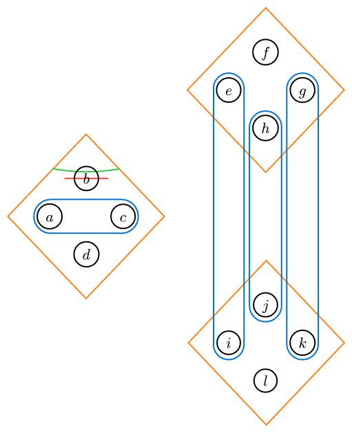
with the code being:
#diagram(
  debug: 0,
  node-shape: circle,
  node-inset: 1.5mm,
  node-outset: 0mm,
  node-fill: none,
  axes: (ltr, btt),
  let diam-radius = 0.6,
  let v2-pos = (3, 2),
  let v3-pos = (3, -2),
  node((-diam-radius, 0), $a$, stroke: black, name: <a>),
  node((diam-radius, 0), $c$, stroke: black, name: <c>),
  node((0, diam-radius), $b$, stroke: black, name: <b>),
  node((0, -diam-radius), $d$, stroke: black, name: <d>),
  //
  node((v2-pos.at(0) - diam-radius, v2-pos.at(1)), $e$, stroke: black, name: <e>),
  node((v2-pos.at(0) + diam-radius, v2-pos.at(1)), $g$, stroke: black, name: <g>),
  node((v2-pos.at(0), v2-pos.at(1) + diam-radius), $f$, stroke: black, name: <f>),
  node((v2-pos.at(0), v2-pos.at(1) - diam-radius), $h$, stroke: black, name: <h>),
  //
  node((v3-pos.at(0) - diam-radius, v3-pos.at(1)), $i$, stroke: black, name: <i>),
  node((v3-pos.at(0) + diam-radius, v3-pos.at(1)), $k$, stroke: black, name: <k>),
  node((v3-pos.at(0), v3-pos.at(1) + diam-radius), $j$, stroke: black, name: <j>),
  node((v3-pos.at(0), v3-pos.at(1) - diam-radius), $l$, stroke: black, name: <l>),
  // 4-element sets partition
  node([], enclose: (<a>, <b>, <c>, <d>), stroke: orange, shape: diamond),
  node([], enclose: (<e>, <f>, <g>, <h>), stroke: orange, shape: diamond),
  node([], enclose: (<i>, <j>, <k>, <l>), stroke: orange, shape: diamond),
  // Easy 2-element sets
  node([], enclose: (<a>, <c>), stroke: blue, shape: pill),
  node([], enclose: (<h>, <j>), stroke: blue, shape: pill),
  node([], enclose: (<e>, <i>), stroke: blue, shape: pill),
  node([], enclose: (<g>, <k>), stroke: blue, shape: pill),
  // 2-element set for b, f nodes
  edge((-0.35, diam-radius), (0.35, diam-radius), stroke: red + 0.35mm, bend: 0deg),
  edge((-0.35, diam-radius), (0.35, diam-radius), stroke: green + 0.35mm, bend: 10deg),
}
where the red line is the starting point and my intent was to bend it until it curved under the b node. For some reason, its positioning changes entirely, as seen with the green arc.
Can anyone help me figure out what is going on here? Thank you.