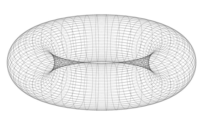
The solution is simple: use rectangles instead of lines. But I wouldn’t use Typst directly for high-resolution 3D stuff, because it’s not really optimized for this and can’t use GPU (yet?) to accelerate anything, if something can be accelerated. Moreover, the drawing part is done with CeTZ, which is an abstraction layer, which will hit performance for intensive tasks.
Since I don’t like geometry, Claude was able to whip up some algorithm for creating torus rectangles’ points, and also for adding shading. I after a bit of re-formatting:
#import "@preview/cetz:0.4.0"
#let draw-torus(
outer-radius: 4,
inner-radius: 1,
theta-divisions: 100, // Steps around major circle.
phi-divisions: 50, // Steps around minor circle.
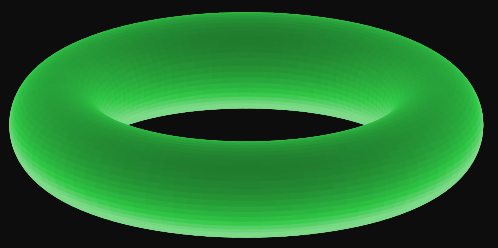
base-color: green,
stroke: auto,
light-direction: (1, 1, 1), // Light source direction
ambient-light: 0.2, // Ambient light intensity (0-1)
diffuse-strength: 0.8, // Diffuse lighting strength (0-1)
) = {
import calc: cos, max, min, pi, pow, sin, sqrt
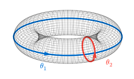
let get-torus-point(theta, phi) = {
let x = (outer-radius + inner-radius * cos(phi)) * cos(theta)
let y = (outer-radius + inner-radius * cos(phi)) * sin(theta)
let z = inner-radius * sin(phi)
return (x, y, z)
}
/// Calculate surface normal at given theta, phi.
let get-torus-normal(theta, phi) = {
let nx = cos(phi) * cos(theta)
let ny = cos(phi) * sin(theta)
let nz = sin(phi)
(nx, ny, nz)
}
let normalize-vector(vec) = {
let (x, y, z) = vec
let length = sqrt(pow(x, 2) + pow(y, 2) + pow(z, 2))
if length == 0 { return (0, 0, 0) }
(x / length, y / length, z / length)
}
/// Calculate dot product of two vectors.
let dot-product(v1, v2) = {
let (x1, y1, z1) = v1
let (x2, y2, z2) = v2
x1 * x2 + y1 * y2 + z1 * z2
}
/// Calculate lighting intensity using Lambertian shading.
let calculate-lighting(normal) = {
let norm-light = normalize-vector(light-direction)
let norm-normal = normalize-vector(normal)
// Lambertian (diffuse) shading.
let diffuse = max(0, dot-product(norm-normal, norm-light))
// Combine ambient and diffuse lighting.
let intensity = ambient-light + diffuse-strength * diffuse
min(1, intensity) // Clamp to [0, 1].
}
/// Interpolate between two colors based on intensity
let shade-color(color, intensity) = {
// Convert intensity to RGB scaling.
// Minimum brightness to avoid pure black.
let scale = max(0.1, intensity)
// For built-in colors, create a lighter/darker version
if type(color) == std.color {
return color.lighten(100% * (intensity - 0.5))
}
// For custom colors, you might need different handling
color
}
for i in range(theta-divisions) {
for j in range(phi-divisions) {
let theta1 = (2 * pi * i) / theta-divisions
let theta2 = (2 * pi * (i + 1)) / theta-divisions
let phi1 = (2 * pi * j) / phi-divisions
let phi2 = (2 * pi * (j + 1)) / phi-divisions
let point1 = get-torus-point(theta1, phi1)
let point2 = get-torus-point(theta2, phi1)
let point3 = get-torus-point(theta2, phi2)
let point4 = get-torus-point(theta1, phi2)
// Calculate normal at the center of the rectangle for lighting
let mid-theta = (theta1 + theta2) / 2
let mid-phi = (phi1 + phi2) / 2
let normal = get-torus-normal(mid-theta, mid-phi)
// Calculate shading intensity
let intensity = calculate-lighting(normal)
// Apply shading to color
let shaded-color = shade-color(base-color, intensity)
cetz.draw.line(
point1,
point2,
point3,
point4,
close: true,
stroke: if stroke == auto { shaded-color } else { stroke },
fill: shaded-color,
)
}
}
}
#cetz.canvas({
import cetz.draw: *
ortho(x: -70deg, y: 0deg, sorted: true, {
draw-torus(light-direction: (0, -1, 1))
})
})
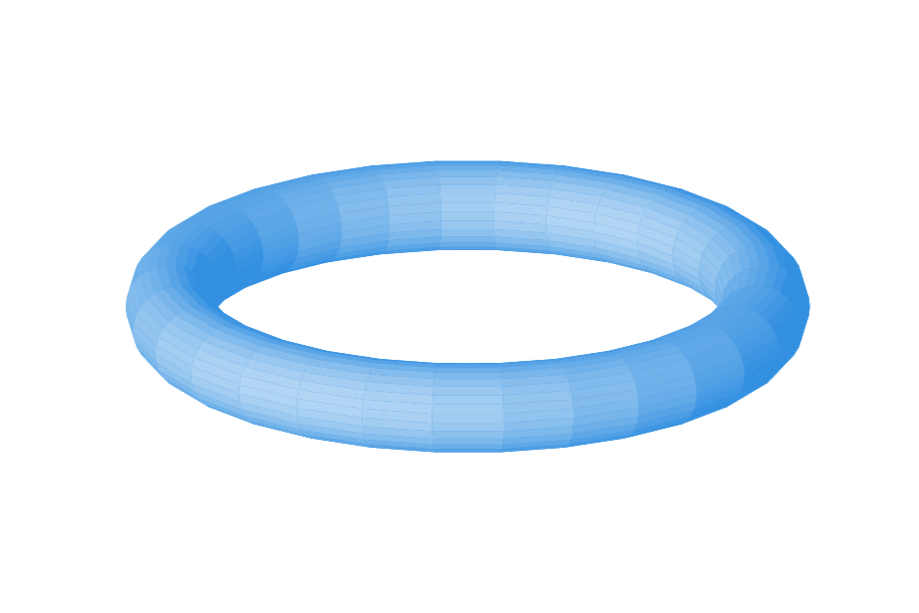
This hi-res torus costed me 1 GiB of RAM and 13 seconds of compilation.
P.S. Light-direction is probably not in sync with ortho, maybe.